
Water & Wastewater · Australia
Armidale Sewerage Treatment Plant
50,000 EP-capacity plant BIM developed around detailed 3D process modelling, project-specific parametric families and multidisciplinary documentation.
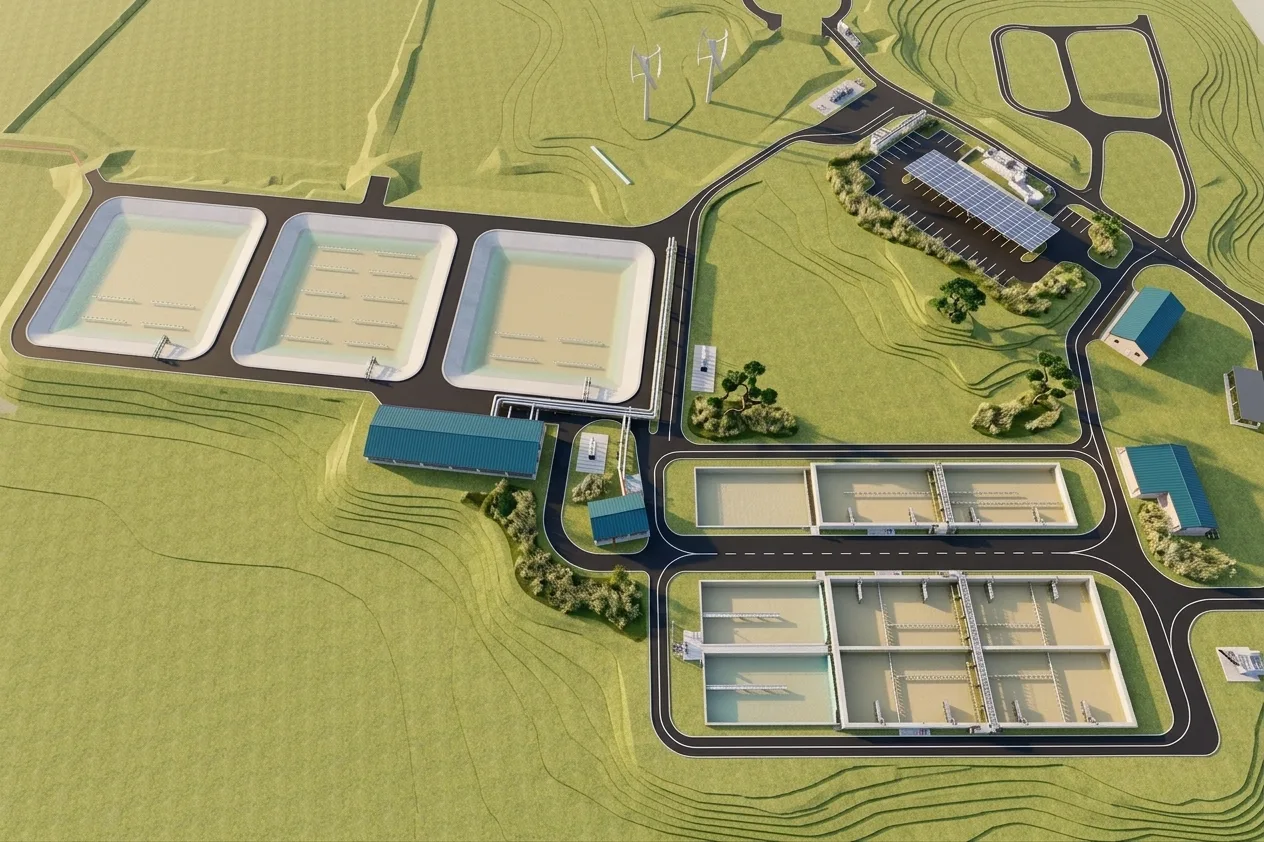
Project Visual50,000 EP Capacity · Australia
Project Overview
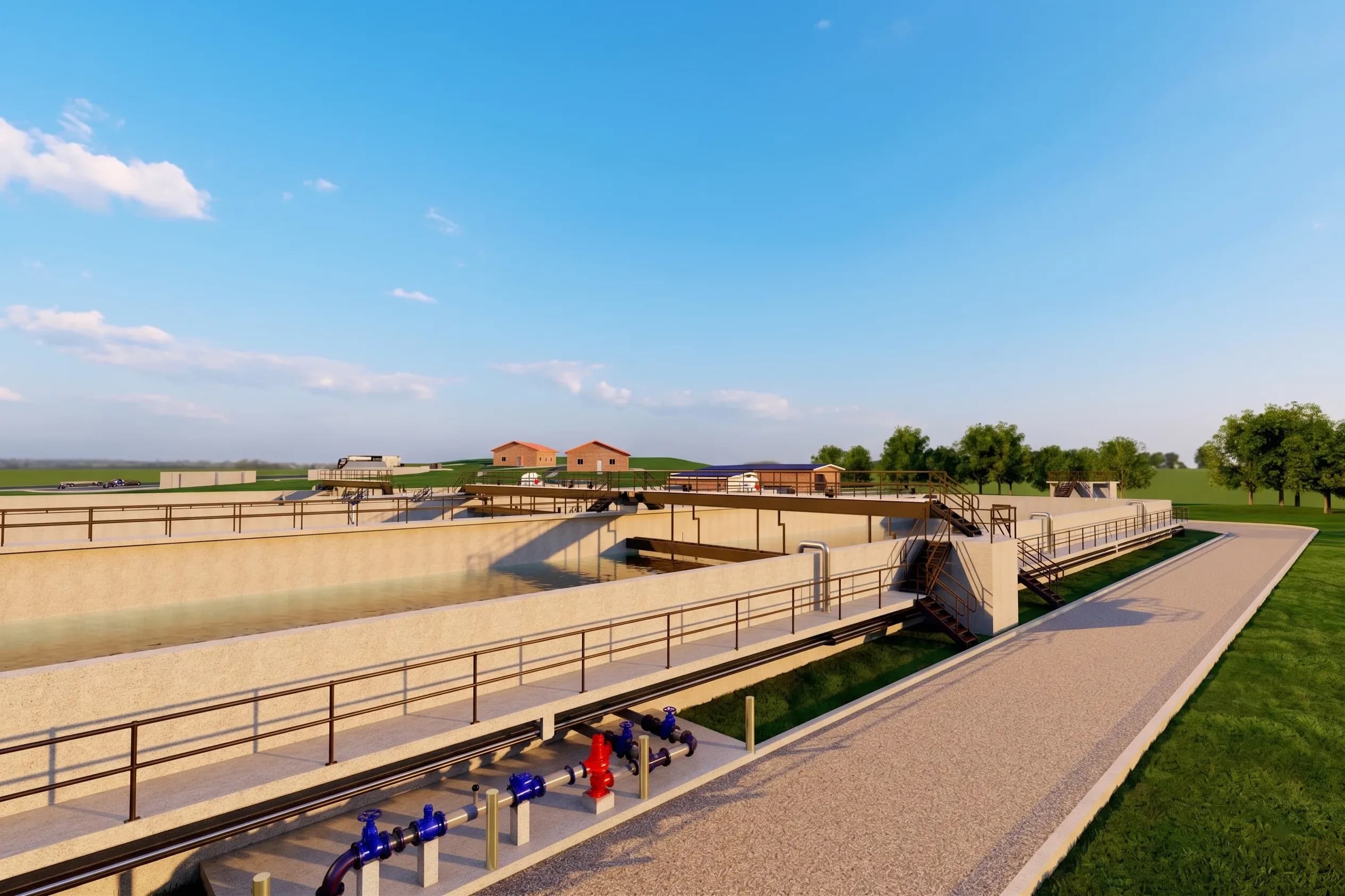
Model the Full Treatment Process as One Understandable Digital Environment.
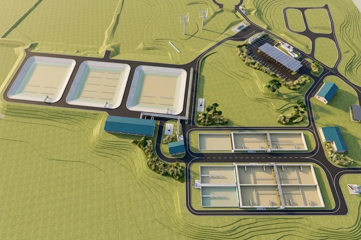
IBS Projects modelled the principal process, building and infrastructure components of the Armidale Sewerage Treatment Plant in 3D. The scope combined treatment-plant geometry with project-specific parametric families and multidisciplinary drawing preparation, creating a detailed BIM package for a 50,000 EP-capacity facility.
What IBS Projects Delivered
Plant Modelling, Custom Components and Technical Documentation.
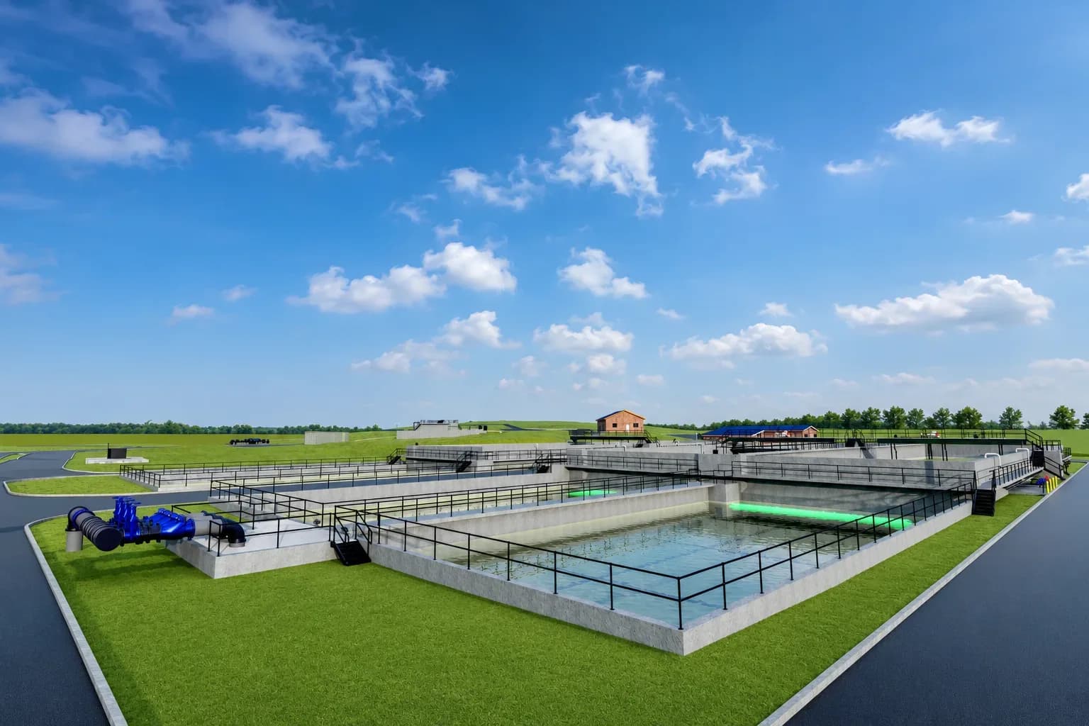
Plant Modelling
Complete 3D Treatment-Plant Model
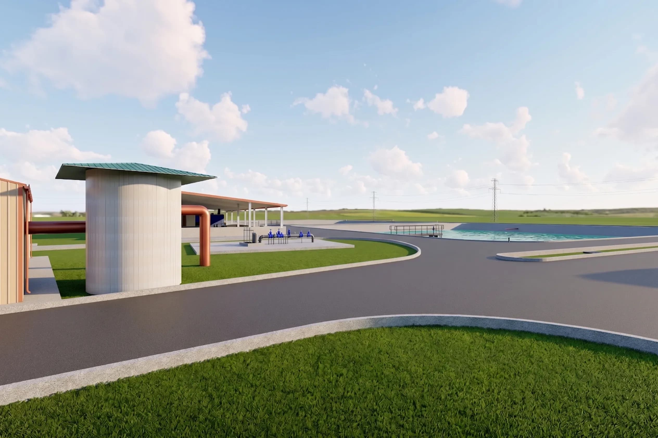
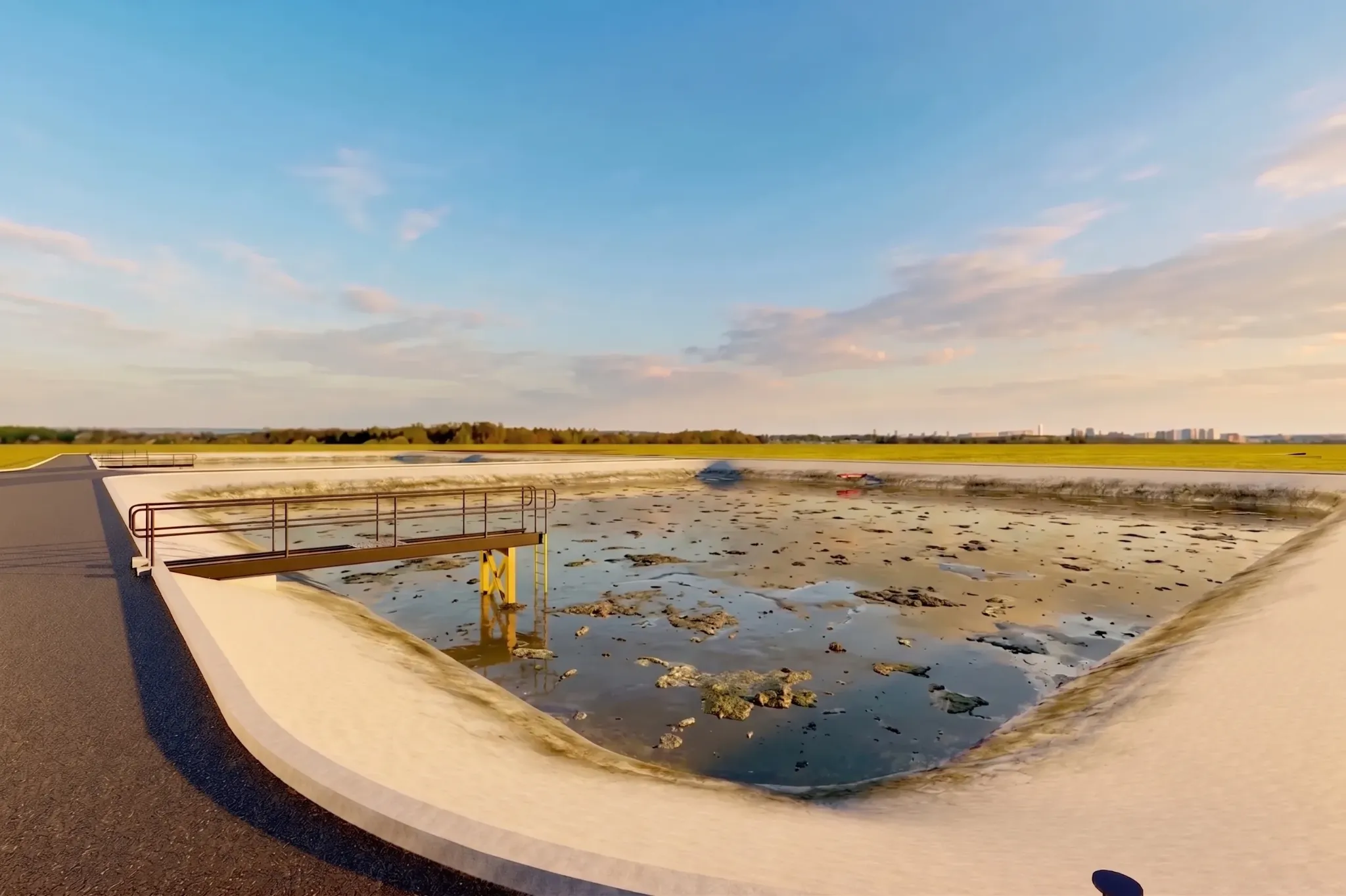
The model covers the plant's principal process and support components, including inlet works, intermittently decanted extended aeration tanks, balance tanks, sludge lagoons, the switch-room building, chemical dosing and UV treatment facilities, and pump stations.Parametric Families
Project-Specific Fittings, Accessories & Handrails
Special pipe fittings and accessory families were created parametrically, together with special handrail families developed to match Monowils requirements.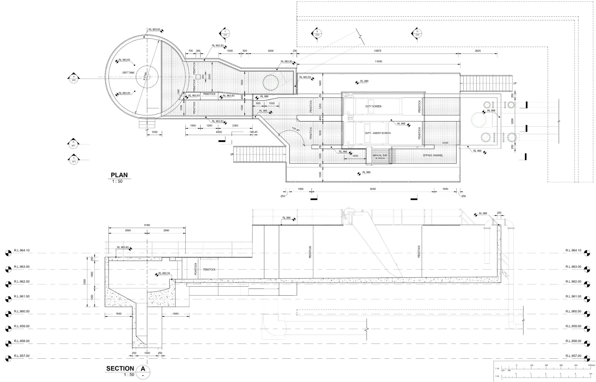
Documentation
Multidiscipline Drawing Preparation
Architectural, mechanical, electrical, plan and structural drawings were prepared from the project information to support a coordinated technical delivery package.BIM · Water & Wastewater
Detail Where Plant Infrastructure Needs It Most.
The project scope extends beyond overall plant massing. Process areas, custom fittings, accessories, handrails and multiple drawing disciplines are represented so the digital delivery reflects the technical character of the facility.
- Inlet works, treatment tanks and balance tanks
- Sludge lagoons, pump stations and switch-room building
- Chemical dosing and UV treatment facilities
- Parametric fittings, accessories and Monowils-style handrails
- Architectural, mechanical, electrical, plan and structural drawings
Project Approach
From Plant Components to a Structured BIM Delivery.
- 01
Plant Scope Review
The treatment-process components, support buildings and required drawing disciplines are defined as one integrated BIM scope.
- 02
3D Model Development
Inlet works, treatment tanks, lagoons, dosing and UV facilities, pump stations and other plant components are developed in 3D.
- 03
Parametric Family Creation
Project-specific pipe fittings, accessories and special handrail families are created to represent the required plant components accurately.
- 04
Drawing Preparation
Architectural, mechanical, electrical, plan and structural drawings are prepared from the developed project information.
Project Gallery
Inside the Armidale Treatment Plant BIM Model.
Planning a Water or Wastewater BIM Project?
Bring the Plant Scope, Drawings and Required Deliverables.
IBS Projects can review your project information and help define the modelling, parametric-family and documentation scope needed for a practical BIM delivery.